
Specification :
- 48W Switching power supply.
- Over temperature protection
- Reverse polarity protection
- +12V at 3A (3000mA) / -12V at 1A (1000mA)
- possible extension for +5V power supply
- Can be configured to -15/+15V
- About 95% efficiency at 24V input
- 8mV ripple
Warning
I’ve got feed-back of unsuccessful build of this power supply. Unfortunately, without having access to the build, I was not able to help or to understand why it was not working. I hope it will work for you but I can not provide assistance.
UPDATE : Some DC/DC regulator are now based on LM2596-5 : THEY WILL NOT WORK. It is very important to check that the board is based on the LM2596-ADJ!
UPDATE 2 : I was told (thanks fg) that only LM2596-ADJ jm88rp, jm74rp or jm84rphs works. hw411 board with LM2596-ADJ jm97rphs don’t works. So I did not recommend using this schematics anymore. I keep this page online only for archive.
UPDATE 3 : Exsiderurgica made a video about this PSU
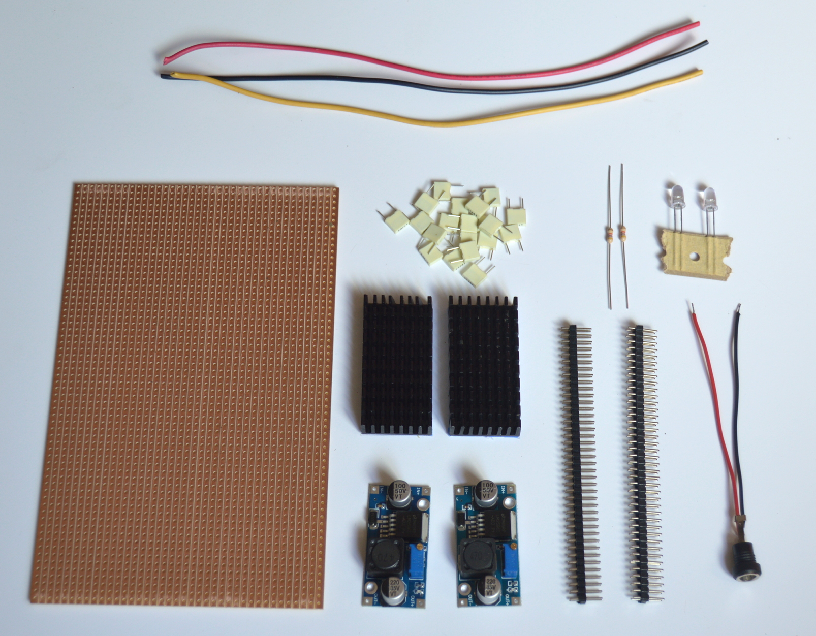
Material to buy
It should cost less than 20€/$ on ebay or other sources.
- 2 x DC/DC regulator based on LM2596-ADJ (it’s very important to use a LM2596-ADJ, not an equivalent, not a LM2596-5)
- 2 x radiator for the LM2596 (with electrical isolating, thermal conductive paste)
- Strip prototyping board (about 10x16cm, 4x6inch)
- 2 x 40 pin 2.54 dual raw male header
- Power connector of your choice
- 20 x 100nF Capacitor
- 2 x Leds and 4.7K resistor (optional)
- Electric cable
Material you should already have
- An old laptop power supply (from 15 to 36V, 80 Watt minimum)
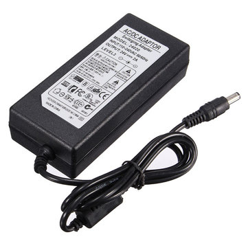
If you don’t own one, you can buy a generic one for cheap.
Needed tools
- Soldering iron
- Various hand tool, screw drivers, etc
- Multi-meter
Instructions
- Read all this documentation BEFORE doing anything else (read the important notes twice!)
- Fix the radiators on the LM2596 modules, and to the board
- Cut in half the PCB board (parallel to the strip)
- Solder the module according to this schematics:
- Plug the power connector
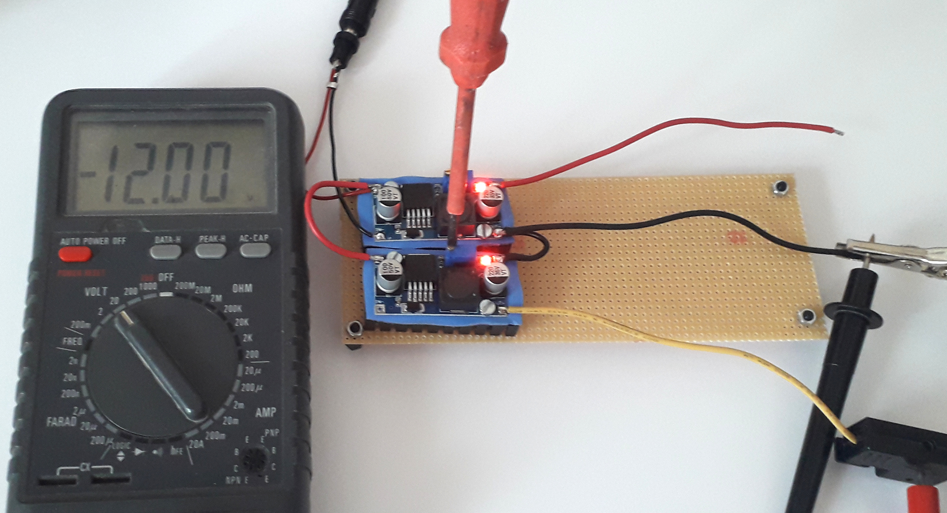
- Adjust the trimer to change the output voltage (adjust to +12V and -12V) using a small screw driver
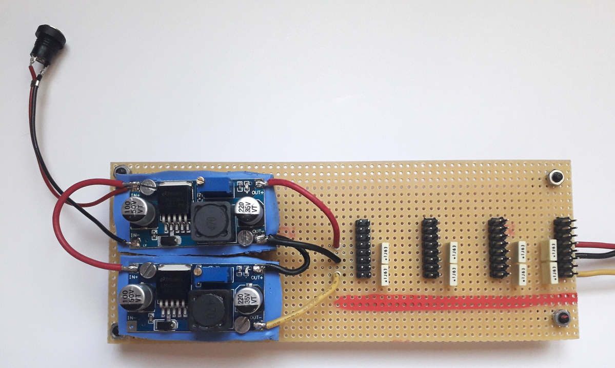
- Cut the pin header to get 10 piece of 2×8 pins
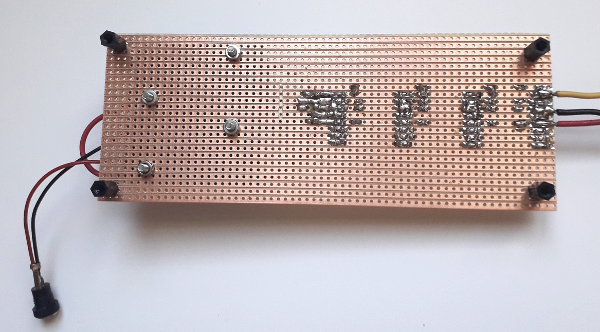
- Solder this pin header one next to each other ON THE SAME RAW of the board, in order to have the electrical connection between them.
- Solder capacitor for each header between -12V and Ground and also between ground and +12V
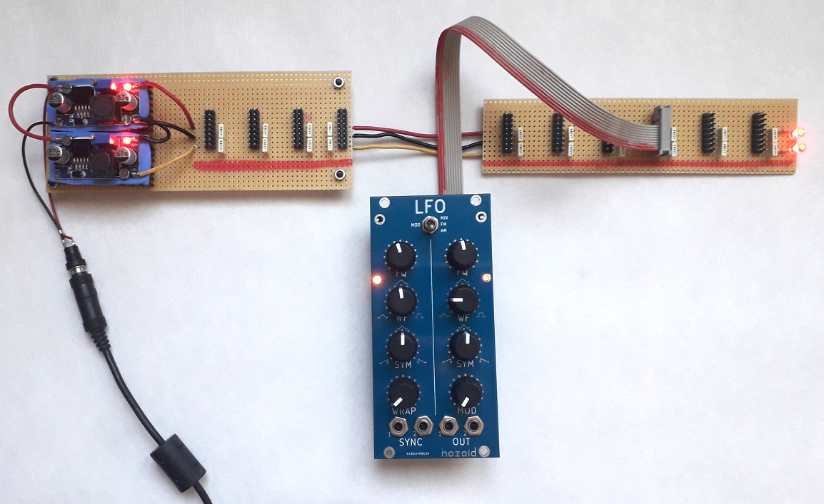
- Use the 2nd half of the PCB for an extension board that you can connect to the 1st board
- Solder the LED and their corresponding resistor if you want a visual feedback of the power supply
The radiator need to be isolated from the LM2596 PCB in order avoid electric shortcut.
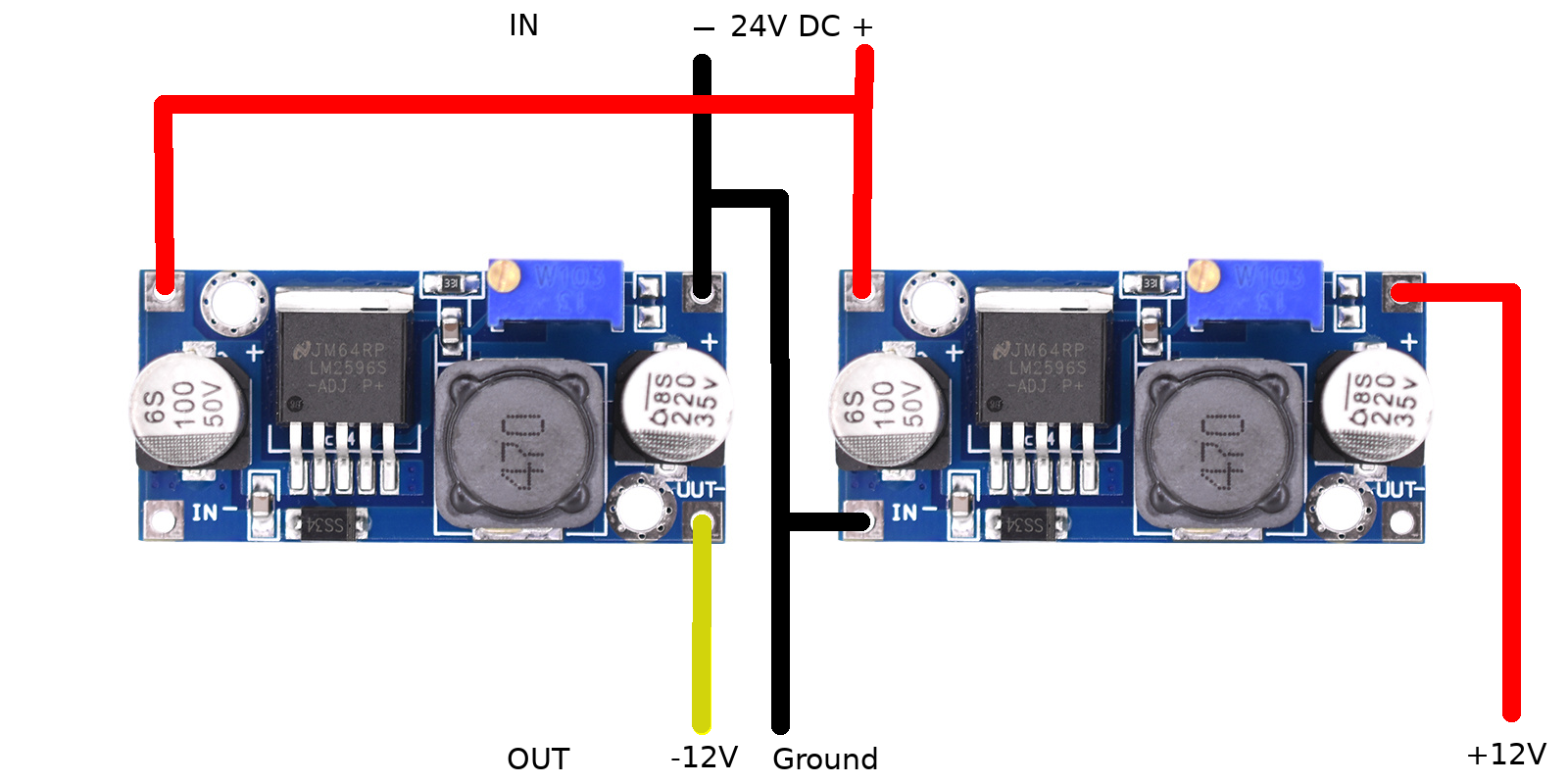
Yes, I know, it’s a strange connection, but it allow to convert the positive power supply to a negative power supply.
IN- and OUT- are connected inside the module, so you should have something that look like this : 

1st raw (the Red one) is the -12V, 2nd, 3rd and 4th raw are the ground (they should be connected together on each connector), 5th raw is the +12V. The other raw should not be connected.
Important notes
- If you only need 2A or less from the power supply, you don’t need to add the radiator.
- If you need a 5V power supply, you can add an other LM2596 module.
- Soldering skill is mandatory in order to build this project, don’t be overconfident about your skill, you could burn your modules.
- If you think this guide is not well documented enough, you should ask for help.
- Test EVERYTHING before plugging the power.
- Double test EVERYTHING before plugging your module.
- Triple test EVERYTHING once again before plugging your module.
- Don’t plug all your modules in the same time, but plug them one after the other.
- I am not responsible in case of malfunction or any consequence of this malfunction.